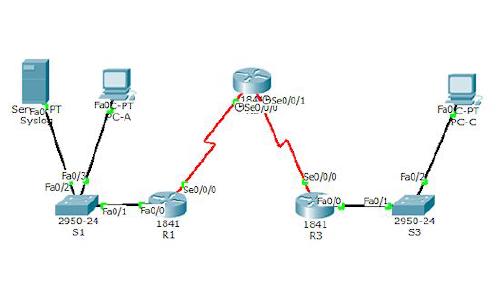
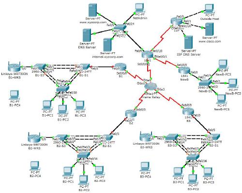
Soluzione PT Activity 5.6.1: Packet Tracer Skills Integration Challenge

Task 1: Configure PPP with CHAP Authentication
Step 1. Configure the link between HQ and B1 to use PPP encapsulation with CHAP authentication.

The password for CHAP authentication is cisco123.

B1
User Access Verification
Password: cisco
B1>en
Password: class
B1#conf t
B1(config)#int s0/0/0
B1(config-if)#encapsulation ppp
B1(config-if)#ppp authentication chap
B1(config-if)#exit
B1(config)#username HQ password cisco123

HQ
User Access Verification
Password: cisco
HQ>en
Password: class
HQ#conf t
HQ(config)#int s0/0/0
HQ(config-if)#encapsulation ppp
HQ(config-if)#ppp authentication chap
HQ(config-if)#exit
HQ(config)#username B1 password cisco123

Step 2. Configure the link between HQ and B2 to use PPP encapsulation with CHAP authentication.
The password for CHAP authentication is cisco123.

HQ
HQ(config)#
HQ(config)#int s0/0/1
HQ(config-if)#encapsulation ppp
HQ(config-if)#ppp authentication chap
HQ(config-if)#exit
HQ(config)#username B2 password cisco123

B2
User Access Verification
Password: cisco
B2>en
Password: class
B2#conf t
B2(config)#int s0/0/0
B2(config-if)#encapsulation ppp
B2(config-if)#ppp authentication chap
B2(config-if)#exit
B2(config)#username HQ password cisco123

Step 3. Verify that connectivity is restored between the routers.
HQ should be able to ping both B1 and B2. The interfaces may take a few minutes to come back up. You can switch back and forth between Realtime and Simulation mode to speed up the process. Another possible workaround to this Packet Tracer behavior is to use the shutdown and no shutdown commands on the interfaces.

HQ
HQ#ping 10.1.1.2

Type escape sequence to abort.
Sending 5, 100-byte ICMP Echos to 10.1.1.2, timeout is 2 seconds:
!!!!!
Success rate is 100 percent (5/5), round-trip min/avg/max = 4/4/6 ms

HQ#ping 10.1.1.6

Type escape sequence to abort.
Sending 5, 100-byte ICMP Echos to 10.1.1.6, timeout is 2 seconds:
!!!!!
Success rate is 100 percent (5/5), round-trip min/avg/max = 2/3/5 ms

Task 2: Configure Default Routing
Step 1. Configure default routing from HQ to ISP.

Configure a default route on HQ using the exit interface argument to send all default traffic to ISP.

HQ
HQ(config)#ip route 0.0.0.0 0.0.0.0 s0/1/0

Step 2. Test connectivity to Web Server.
HQ should be able to successfully ping Web Server at 209.165.202.130 as long as the ping is sourced from the Serial0/1/0 interface.

HQ#ping 209.165.202.130

Type escape sequence to abort.
Sending 5, 100-byte ICMP Echos to 209.165.202.130, timeout is 2 seconds:
!!!!!
Success rate is 100 percent (5/5), round-trip min/avg/max = 7/7/9 ms

Task 3: Configure OSPF Routing
Step 1. Configure OSPF on HQ.

- Configure OSPF using the process ID 1.
- Advertise all subnets except the 209.165.201.0 network.
- Propagate the default route to OSPF neighbors.
- Disable OSPF updates to ISP and to the HQ LANs.

HQ
HQ(config)#router ospf 1
HQ(config-router)#network 10.1.1.4 0.0.0.3 area 0
HQ(config-router)#network 10.1.1.0 0.0.0.3 area 0
HQ(config-router)#network 10.1.50.0 0.0.0.255 area 0
HQ(config-router)#network 10.1.40.0 0.0.0.255 area 0
HQ(config-router)#default-information originate
HQ(config-router)#passive-interface S0/1/0
HQ(config-router)#passive-interface f0/0
HQ(config-router)#passive-interface f0/1
HQ(config-router)#exit

Step 2. Configure OSPF on B1 and B2.

- Configure OSPF using the process ID 1.
- On each router, configure the appropriate subnets.
- Disable OSPF updates to the LANs.

B1
B1(config)#router ospf 1
B1(config-router)#network 10.1.1.0 0.0.0.3 area 0
B1(config-router)#network 10.1.10.0 0.0.0.255 area 0
B1(config-router)#network 10.1.20.0 0.0.0.255 area 0
B1(config-router)#passive-interface f0/0
B1(config-router)#passive-interface f0/1
B1(config-router)#exit

B2
B2(config)#router ospf 1
B2(config-router)#network 10.1.1.4 0.0.0.3 area 0
B2(config-router)#network 10.1.70.0 0.0.0.255 area 0
B2(config-router)#network 10.1.80.0 0.0.0.255 area 0
B2(config-router)#passive-interface f0/0
B2(config-router)#passive-interface f0/1
B2(config-router)#exit

Task 4: Implement Multiple ACL Security Policies
Step 1. Implement security policy number 1.

Block the 10.1.10.0 network from accessing the 10.1.40.0 network. All other access to 10.1.40.0 is allowed. Configure the ACL on HQ using ACL number 10.
Use a standard or extended ACL? standard
Apply the ACL to which interface? f0/1
Apply the ACL in which direction? OUT

HQ
HQ(config)#access-list 10 deny 10.1.10.0 0.0.0.255
HQ(config)#access-list 10 permit any
HQ(config)#int fa0/1
HQ(config-if)#ip access-group 10 out

Step 4. Implement security policy number 2.
Host 10.1.10.5 is not allowed to access host 10.1.50.7. All other hosts are allowed to access 10.1.50.7. Configure the ACL on B1 using ACL number 115.
Use a standard or extended ACL? extended
Apply the ACL to which interface? f0/0
Apply the ACL in which direction? IN

B1
B1(config)#access-list 115 deny ip host 10.1.10.5 host 10.1.50.7
B1(config)#access-list 115 permit ip any any
B1(config)#int fa0/0
B1(config-if)#ip access-group 115 in

Step 7. Implement security policy number 3.
Hosts 10.1.50.1 through 10.1.50.63 are not allowed web access to Intranet server at 10.1.80.16. All other access is allowed. Configure the ACL on the appropriate router and use ACL number 101.
Use a standard or extended ACL? extended
Configure the ACL on which router? HQ
Apply the ACL to which interface? f0/0
Apply the ACL in which direction? IN

HQ
HQ(config)#access-list 101 deny tcp 10.1.50.0 0.0.0.63 host 10.1.80.16 eq www
HQ(config)#access-list 101 permit ip any any
HQ(config)#interface fa0/0
HQ(config-if)#ip access-group 101 in

Step 10. Implement security policy number 4.
Use the name NO_FTP to configure a named ACL that blocks the 10.1.70.0/24 network from accessing FTP services (port 21) on the file server at 10.1.10.2. All other access should be allowed.
Note: Names are case-sensitive.
Use a standard or extended ACL? extended
Configure the ACL on which router? B2
Apply the ACL to which interface? f0/1
Apply the ACL in which direction? IN

B2
B2(config)#ip access-list extended NO_FTP
B2(config-ext-nacl)#deny tcp 10.1.70.0 0.0.0.255 host 10.1.10.2 eq ftp
B2(config-ext-nacl)#permit ip any any
B2(config-ext-nacl)#interface fa0/1
B2(config-if)#ip access-group NO_FTP in

Step 12. Implement security policy number 5.
Since ISP represents connectivity to the Internet, configure a named ACL called FIREWALL in the following order:
Allow only inbound ping replies from ISP and any source beyond ISP.
Allow only established TCP sessions from ISP and any source beyond ISP.
Explicitly block all other inbound access from ISP and any source beyond ISP
Use a standard or extended ACL? extended
Configure the ACL on which router? HQ
Apply the ACL to which interface? s0/1/0
Apply the ACL in which direction? IN

HQ
HQ(confi)#ip access-list extended FIREWALL
HQ(config-ext-nacl)#permit icmp any any echo-reply
HQ(config-ext-nacl)#permit tcp any any established
HQ(config-ext-nacl)#deny ip any any
HQ(config-ext-nacl)#interface s0/1/0
HQ(config-if)#ip access-group FIREWALL in

This post is also available in: Inglese

Lascia un Commento

L'indirizzo email non verrĂ  pubblicato. I campi obbligatori sono contrassegnati *

Immagine CAPTCHA

*

È possibile utilizzare questi tag ed attributi XHTML: <a href="" title=""> <abbr title=""> <acronym title=""> <b> <blockquote cite=""> <cite> <code> <del datetime=""> <em> <i> <q cite=""> <strike> <strong>